cze 132022
 

After a long time it’s time for a big upgrade of my computer hardware orchestra. Here it is! The bigger and better Floppotron 3.0. 512 floppy disk drives, 4 scanners and 16 hard disk drives.

My noise-making contraption grew a little bit since last update. It has its own „studio” space and became a relatively complex device. There is a ton of cables, a lot of custom electronic circuits, but the whole power is in the firmware which has been rewritten from scratch. In this article I’ll try to explain the principle of operation, how it’s built, how the whole system works, what’s still missing, provide some more technical details for nerds and answer the most commonly asked questions.

So how does it all work?

To avoid scaring the non-technical readers away at the beginning, I’ll start with the basic operating principles and explain where these sounds come from. Every mechanical device with electric motor or any other moving parts makes noise as a side effect. Sometimes that noise can be controlled. and turned into music – which usually involves some level of abuse. All of the devices present in the „orchestra” contain either stepper motors or moving heads (in case of hard drives), which are driven by custom electronic circuits – controllers. Those controllers are connected in a network and can be commanded from the computer to make a specific device (e.g. scanner #2) emit a specific sound (e.g. constant 440hz tone which corresponds to A4 note in music) at a specific point in time. A sequence of those noises and tones makes music – just like with the real instruments. Sounds simple? In principle, yes, but it gets complicated in a larger scale.

How it’s done?

The machine evolved into a relatively large system with multiple custom circuit boards and 3D-printed parts. While making the new Floppotron, one of the main priorities (if not the main) was finishing it in reasonable time. It’s still a hobby project made after hours and not something commercial or mass produced, so you will find some nice solution as well as some janky, quick-and-dirty ones – and that’s the beauty of hobby projects. Let’s get a little more technical. To explain how the system works, I’ll go through the overview first and then will get into details of each individual block. Here’s a simplified schematic od the machine.

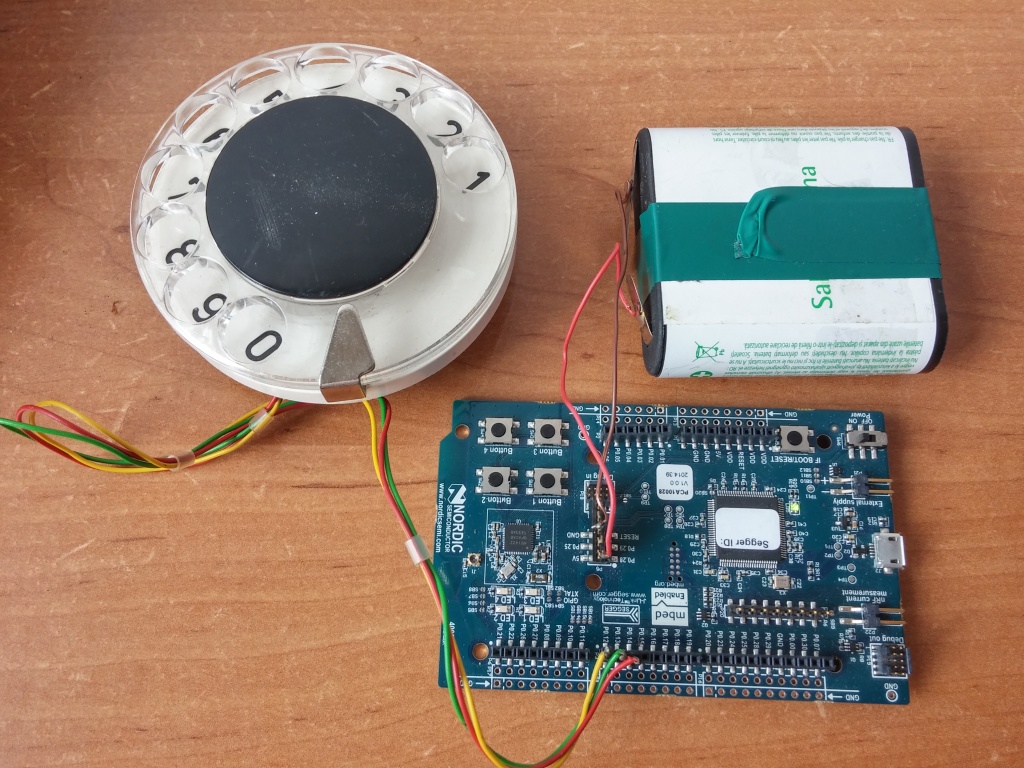
To make the old computer hardware play, we need a set of electronic controllers mentioned before but also a proper music (musical sequence) to play. A melody is encoded as a sequence od MIDI events, the same format as all digital synthesizers use. MIDI does not carry any actual audio data, but just short events, like pressing a piano key or twisting a control knob – you can think of it as a digital form of sheet music. Those events are send from the computer to the gateway using USB to MIDI adapter. The gateway is a custom nRF52 microcontroller based device which sits between the PC with MIDI adapter and the network of „instrument” controllers. It receives MIDI data and converts that data to RS-485-based internal protocol which can encapsulate MIDI and some extra stuff. The gateway, protocol and reasoning is described in further section. Those messages are picked by controllers which will turn the digital information into a sound by driving the electric motors or moving the hard disk heads. The controller consists of a common MCU board with Nordic nRF52832 chip and a driver boards specific to the „instrument”, like floppy drive string, flatbed scanner or a hard drive. If you’re wandering why there is a Bluetooth-enabled chip – I’ll explain it too, but let’s talk about how the sound is created first.

Floppy disk drive wall

A floppy disk contains a magnetic disk inside which is read and written by the drive (FDD). The data is stored by the magnetic head being moved over the spinning disk surface which incorporates two motors. One in the middle of the drive which spins the disk around and a second one driving the linear mechanism which slides the head across the disk radius. It’s the latter, stepper motor which makes that specific FDD seek sound. The head assembly is moved back and forth in small steps and each of those steps make a click. If the step rate is high enough, it is perceived as a constant tone with its pitch depending on movement speed.

   
The controller software takes care of driving multiple disk drives at once to step its heads with requested frequency. There is also one more thing which makes it sound good and more natural – it’s the sound envelope simulation. The drives are grouped in columns by the software and the whole column can only play one tone at a time, but with varying number of drives playing. By changing the number of active drives I can make the tone volume change over time and mimic piano keystrokes or plucking guitar string which volume decays exponentially. The envelope can also be used to get other nice sounding effects, like vibration (sinusoidal envelope), etc.

Driving a single FDD is easy, as it provides a simple digital interface to control the head position on its 34-pin connector. To move the head, only 3 signals are required – EN (enable), DIR (direction) and STEP. The head step is performed on falling edge of STEP signal in a direction selected by DIR pin state, provided that EN is active (logical „0”), which also lights the LED on the front of a drive. Connecting and driving a larger amount of drives makes it a little more complicated.

 
To connect that many drives, I made a set of daisy-chained adapter boards containing buffers and shift registers (driven with SPI) providing more outputs. Generating the signal sequences for that many drives is tricky, but I was able to get a pretty god performance with some programming tricks and by using PPI (a special peripheral present in Nordic chips) to offload a signifiant part of the signal generation from the CPU. In current configuration, one controller drives up to 192 drives, so I’m using 3 controllers to drive 512 FDDs. More drives per controller is still possible with some further optimization (to keep the satisfying timing resolution), but it’s not really needed at this point.

     
The FDD wall is made of 8-drive blocks tied together with 3D-printed rails. Every block has one adapter (assembled in local SMT manufacturing facility) plugged into the first drive. The remaining seven drives are connected to the adapter outputs with hand-made cables terminated with Dupont connectors. The cabling was the most tedious part. I was planning to order such cables in a local factory, but due to lead time exceeding a couple of month I decided to go a quick-and-dirty way. I have ordered a bag of so-called rainbow cables in hobby shop, removed the 1×1 plastic connectors with a knife ((512 – 64) drives * 4 wires * 2 sides!) and put the larger 2-row connectors. I was also initially experimenting with a multiple IDC 2,54 connectors on a single ribbon cable (to avoid cable mess like in previous FLoppotron) – it went pretty good, but required assembly of tinny PCB adapter for every drive which would also increase time and costs. I went with the solution which maybe does not look that cool, but was faster, hassle-less, and cheaper. I couldn’t find any pre-made cables for FDD power, so I had to make those cables and crimp the connectors by hand. Every stack of drives has a 3D printed base which holds the controllers and power boards with resettable fuse. There is one dedicated resettable fuse with indicator LED per each 8-drive block, so failing (shorting) drive with shutdown the block until the short is removed. That protects the cables and makes the replacements of (up to 30-year old) failed drives easier – which, by the way, do fail occasionally. Plastic base with thin plastic rails is not the sturdiest construction, but that will do for now.


Flatbed scanners

The floppy disk drives do a good job playing low pitch tones, but does not handle high notes well. It’s a task for flatbed scanner motors. They have larger motors and can play higher pitch sounds. To drive the scanner motors, I have build a prototype driver using one of my previous prototype output boards combined with off-the-shelf H-bridge modules mounted on a 3D-printed frame. There are four old HP scanners, almost identical as the larger on in Floppotron 2.0 – it took me quite a bit to hunt them on eBay and local Polish advertisement sites. At the moment, it works in the same way as in the previous Floppotron – the controller moves the scanner head assembly using stepper motor with varying speed and alternating direction to avoid bumping against the chassis. It still does not have endstop switches and cannot automatically position itself in the center on power-up – that’s something I want to implement in the next hardware update.

  
However, there are two new features. The first one is the nice looking, neon-like silicon RGB LED strip mounted on each scanner head. In addition to aesthetics, it helps in identifying which device is actually playing which section by pulsing with the notes. The strips are press-fitted into a 3D-printed rails replacing a part of metal housing and scanner mirror assembly. The second new feature comes with the entirely new software and MIDI support – pitch and modulation effects has been improved. Now the scanners can make even more weird sounds.


Hard disk drives

The clicking sound of the hard disks is produced by energizing the coil in the magnetic head assembly. That head is effectively a speaker – but unlike in case of speakers, the element being moved is an arm with magnetic read/write head instead of a speaker cone. In normal operation, the head is moved back and forth over disk platters within the safe operating region. When pushed too far, it will hit the boundary and make a loud click – something you really don’t want to happen with a live hard drive storing your data.

Some time ago I bought a couple of small lots of random old hard drives on eBay-like services. Every drive model has slightly different mechanics, has a different metal casing and therefore make a different sound when abused. To make the set of hard disks sound a little more like a drumset, I had test each drive and sort them by sound they make. Some drives make a bassy „clack”, some of them make higher „bang” and some of them sound like a bell. Each one of 16 drives in current setup has been assigned to a closest General MIDI drum sound it can mimic, e.g. kick drum, snare or closed hi-hat.

    
Unlike the scanner controller, the hard disk controller is more complete. The controller is a bundle of boards tied with wires and 3D-printed prototype frames. There is a single common controller board with dedicated software (as in all other controllers), and a chain of custom H-driver boards in pair with off-the-shelf voltage regulator board (with a cheap clone of LM2576/LM2596/etc) – one pair per every group of 4 drives.

To connect HDD heads I have used modular 6p6c (RJ12) connectors (which are very common and easy to crimp) and a flat 6-conductor phone cable I had laying around. It’s not the best way to carry power due to its thin wires and high resistance, but it’s way thinner by common UTP cable and running 16 of those on a table look way more clean. Aesthetics are also important in this kind of project, so if it works – it’s good enough. Every hard disk has been equipped with a tiny hand-soldered board containing RGB LED and a cable connector. As with scanners, the flashing LEDs help identify which drives are playing.


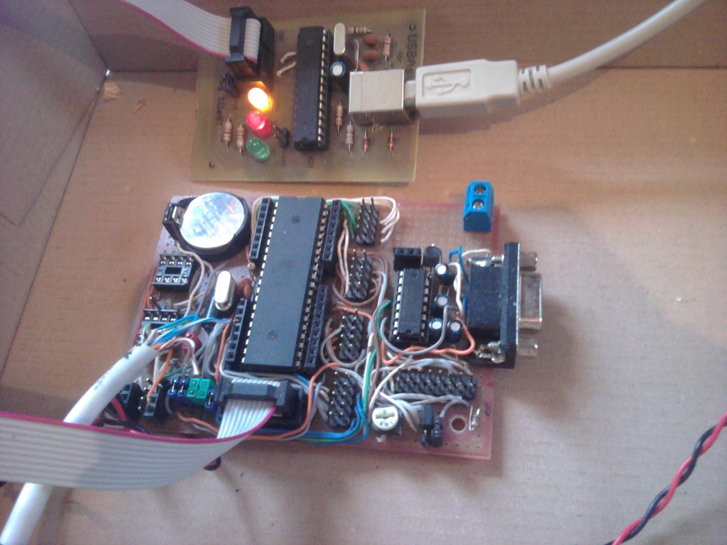
Controllers, gateway and communication

The instruments are exposed to the PC as a MIDI device using USB-MIDI adapter connected the gateway – another custom device with 3D-printed case. I wanted to connect all the instrument controllers in star topology (instead of a daisy-chain as it could be done with MIDI), so I built a converter box with MIDI interface on one side and RS485 network on the other side. With that architecture, the orchestra can be up-scaled easily.

As a connectors I have used modular RJ45s which provide data and +12V power to the controllers. RS485 lines are shared, so controllers have two RJ45s and can be daisy-chained to shorten the cable run. While a passive MIDI-RS485 converter could technically work (as MIDI is a serial interface with a current loop), I made it more complex to get features like checksums, etc. The converter is based on nRF52840 module and a custom baseboard with MIDI/RS485 transcievers and connectors. The software converts MIDI serial data to internal RS485 protocol at higher baudrate (a similar protocol to Modbus). It also has some more features like scanning the internal network and even software updates of controllers behind the gateway over MIDI. It can also be expanded in future. NRF52840 has USB device hardware, so USB-MIDI could optionally be implemented directly in the gateway to bypass low MIDI baudrate limitation (31250) in case of adding multiple new devices into the network. DMX lighting over MIDI is also a possible option.

    
The controllers include a common MCU boards and instrument-specific driver circuits. For a quick and easy development, I have picked a platform I know well and have worked with for a couple of years on daily basis – nRF52 (Nordic Semiconductor) ARM Cortex-M microcontrollers. It’s a Bluetooth LE-enabled MCU family (which I’m not using in this project) with a couple of other very useful features. The main two worth pointing out are fully remappable pins and PPI peripheral which allows to trigger actions by events generated by other peripherals without CPU interaction.

Great power comes with great energy bill!

With increased size, power demand has also increased significantly. Two PC ATX power supplies are not going to cut it anymore. While scanner moors and hard disk heads don’t need a lot of power, 512 Floppy disk make the numbers go high. One drive consume a relatively large amount of power when making noise – up to 2-2,5W (0,4-0,5A at 5V) depending on drive model and frequency. One stack of 32 drives can draw up to around 16A of current when all drives are active. In a typical use case the average current is lower, usually 20-30% depending on music being played. The whole stack is (usually) active for only a short period of time as the controller varies the number of playing drives to alter the sound volume in time. Adding the numbers – 16 stacks may theoretically consume 1,28kW in peak (I have measured at most around ~1,15kW with all 512 drives buzzing).

     
To power the drives, I have used an array of 16 modular 5V/18A power supplies – 18A of continuous current provides a large buffer, even if I wanted to go 100% power for some reason. Every module has built-in over-temperature and short protection. The smaller modules have some advantages over larger PSU with higher specs (>200W) which fit this project very well. They are cheap ($18-$20 each), they have no fans, and the case is low-profile so the modules can be placed on 1U rack shelf. I have considered mounting those modules behind every FDD stack to avoid thick cables for up to 16A, but have eventually decided to install them on perforated 1U shelves inside of 19″ rack cabinet. That turned out to be a good decision, because there is no high voltage cables outside the rack, switching mode supplies can become noisy under load (especially when there are 16 modules) and the biggest advantage – case was built without putting much effort using off-the-shelf parts. There are also some extra aesthetic elements – 3D-printed front panels for PSU modules. I have designed the 3-part panels in Fusion 360 and printed them with Prusa MK3s 3D-printer on a textured base plate. If you’re curious about the labels – I made them by printing the texts on the bottom layer and switching filaments. In general, 3D-printer did a nice job in this project.

        
One suspicious thing in the above pictures that might have caught your attention is the cable color. Yes, that’s a 4mm² speaker cable. I know, I know, that definitely does not meet the safety standards because of the insulation thermal parameters… but it’s not an industrial machinery. …and the cable was pretty cheap. At least it’s a pure copper cable, not one of that coated aluminum crap. The cables are terminated with fat 6,35mm connectors which can handle the maximum load. The whole cabinet is protected with softstart module. That prevents the PSU module array with high input capacitance from tripping the breaker on powerup.

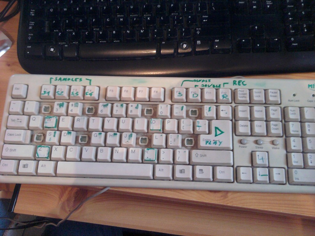
How the music is made?

The device is MIDI-compatible, which means I can use any music composer software which can output MIDI or save MIDI files. Note sequences are encoded as MIDI events, placed on up to 16 tracks. Each track can be assigned to a specific section in the orchestra by changing its program (instrument) parameter. The specific floppy drive stacks play bass tracks, guitar or piano tracks and some of the drum sounds. Hard disks are assigned to drums and scanners play lead tracks. Instruments (or program numbers) can be selected from the list in any MIDI editing software.

To create an arrangement, I usually start with already existing MIDI file. If I cannot find one, I have to make it from scratch – from hearing or using sheet music when available. Even if there is an existing MIDI for a specific song, re-arranging it for The Floppotron is still a time consuming process. Every „instrument” in the setup have its limits and the track must fit the note range it can play. Making a track sound good on the stacks of FDDs or a scanner usually involves a lot of tweaking. I also spend some time to add the fine details, like slides (portamento) or vibratos to mimic the quirks in vocal or guitar parts of original songs – these has to be recreated by ear. Making one arrangement for 3.0 usually takes me 3-4 evenings, which is a little longer than for the older Floppotron 2.0.

Other software

Along with the controller firmware, there is also some software on the PC side. Controllers are configured using dedicated application written in Python. It allows me to set the parameters like connected instrument type or MIDI mapping table. It can also update the firmware in every controller over MIDI port.

There is also one more application used for visuals only – a colorful retro-looking text terminal showing the machine status. It’s also a Python application using Urwid TUI library (running under Cygwin/XTerm on Windows).

What’s next?

The next step will be making some videos with the new setup. There are also some minor software bugs to fix and some missing stuff to add – like endstops for scanners. In the future, I’m planning to add some new instruments, like dot matrix printer and maybe some automated lighting. We’ll see.

More music covers coming soon!

sie 092015
 

After a long break I decided to reactivate the blog. This time I have a nnew, even more useless invention – an unusual bluetooth accesory.

Most of you probably use smartphones with touch screens, but some people still prefer classic mobile phones. Now you dan dial the numbers from your little notebook just like in the good, old days!

The device is based on Nordic Semiconductor nRF51422 chip (NRF51 DK board). It is recognized as a bluetooth keyboard, so no additional software is required. All you need is a phone with Bluetooth 4.0 Low Energy (BLE) support. The firmware is a modiffied HID keyboard example from the SDK, so it took me only about an hour to add a rotary dial support. The dial itself which generates the pulse dial signal was taken out of an old phone. The board could be powered from a 3V coin cell battery, but I have connected a large, flat, 4,5V battery because small coin batteries are not hipster enough!

You can get the source code below. NRF51 SDK 8.0.0 is required to build(available here). I have built it with Keil 5, but it should also work with ARM GCC or IAR compilers.

  Pobierz plik: nrf_rotary_dial.zip
  Rozmiar: 3.65 MB
Warning: mysqli_num_rows() expects parameter 1 to be mysqli_result, boolean given in /home/ebiwptr/silent/home/filedb.php on line 99

gru 272011
 

[English translation below]

Z powodu braku czasu ostatnio nic nie pisałem. Przyszły święta i znalazłem chwilę na rozbudowę poprzedniego projektu cieszącego się sporą popularnością. Oto obiecany powrót stacji dyskietek. Tym razem jest ich aż 8, a obok nich mój panel LED 64×16, nad którym ostatnio pracowałem. Z okazji świąt… świąteczna piosenka:

Planuję napisać coś więcej na temat zasady działania oraz budowy „dyskietkowej orkiestry” oraz odpowiedzieć na najczęściej zadawane pytania, ale już nie dzisiaj – to jest temat na większy artykuł. Niedługo pojawią się kolejne melodie – subskrybuj mój kanał YouTube!

Wesołych Świąt!

—————————————-

I didn’t wrote anything since october because I was very busy last 3 months. Now I have a few free days so here’s the new video – as promised. Floppy drives are back. This time there’s 8 drives and my 64×16 LED display I was working on recently. It’s Christmas time, so… here’s some Christmas song:

I am planning to write some more detailed description of how it works, FAQ and responses and maybe the instructions how to build the „floppy orchestra”, but not today. It’s a topis for separate long article. There will be more floppy music soon, so come back later or subscribe my YouTube channel.

Merry Christmas!

wrz 292011
 

Hello! Here’s an English translation of my previos post. My English isn’t perfect so there might be some mistakes ;-).

Summer holidays are comming to an end, I have passed all september exams and now I am procrastinating doing some dumb things instead finishing two other, more serious projects ;-).
Here’s what polish AGH University of Science and Technology students do in their free time. I’d like to introduce my another, totally useless device – a musical floppy drives.

First attempt:

And now it’s time for the double:

How does it work?

It’s nothing new and it’s very simple. The sound comes from a magnetic head moved by stepper motor. To make a specific sound, head must be moved with appropriate frequency.
FDD has a simple interface – the description may be found for example [ HERE ]. To move the head you need to activate the drive by pulling the DRVSB0 or 1 (depends on the cable you have and the connector – notice the crossover on the FDD ribbon cable) pin low and then falling edge on STEP pin makes the head move one step in direction dependent on DIR pin state.
An ATMega microcontroller is generating those frequencies and it makes the drives play music.

Now it’s tome to call some older buddies (5,25′ or 8′ drivers) and make an orchestra!

wrz 252011
 

Niedawno złożyłem mały próbny panel 32×8, w celu zapoznania się z nowymi tajwańskimi 😉 sterownikami LED. Próby wyszły całkiem nieźle, a testowy wyświetlacz postanowiłem do czegoś wykorzystać. Wygrzebałem plugin do Winampa, który kiedyś napisałem na szybko i połączyłem go z tym wyświetlaczem. Całość prezentuje się całkiem nieźle, panel świeci mocnym jednolitym światłem, więc postanowiłem go Wam pokazać.

Na koniec smutna wiadomość. Schematów i źródeł nie będzie.

wrz 252011
 

[English translation available HERE]

Wakacje się kończą, egzaminy w „kampanii wrześniowej” zaliczone, a ja zamiast kończyć dwa komercyjne projekty zajmuje się głupotami – bo jak wiadomo głupoty cieszą najbardziej 😉 .
Oto, co robią studenci AGH w Krakowie w wolnym czasie. Przedstawiam mój kolejny, kompletnie bezużyteczny wynalazek – grające stacje dyskietek.

Pierwsza próba:

A teraz czas na duet:

Nie jest to nic nowego. Zasada działania jest bardzo prosta. Dźwięk powstaje poprzez ruch głowicy, która jest przesuwana krokowo z odpowiednią częstotliwością. Opis interfejsu można znaleźć np. TUTAJ. Wystarczy jedynie aktywować stację przez podanie stan niskiego na DRVSB0 lub 1 (w zależności czy mamy taśmę z crossem i do której wtyczki podłączona jest stacja) i wybrać kierunek ruchu głowicy (stan niski\wysoki na DIR), a zbocze opadające na STEP spowoduję ruch głowicy o jeden krok. Całością steruje mikrokontroler ATMega.

Teraz tylko pozostało zgromadzić kilku starszych kumpli (5,25′) i stworzyć orkiestrę! 😉

cze 042011
 

Sesja się zbliża, więc tradycyjnie zacząłem już prokrastynować (a Wy? 😉 ). Ostatnio zacząłem pisać bibliotekę do obsługi klawiatury PS/2 w C dla AVR i postanowiłem na szybko w godzinkę lub dwie stworzyć jakiś praktyczny projekt w celu jej przetestowania. Początkowo nie planowałem tego publikować, ale pokazałem to kilku osobom i się spodobało, więc być może spodoba się i Wam. Mi zabawa tym wynalazkiem sprawia radochę jak dziecku 😉 .

Oto moje elektroniczne „pianino” z komputerowej klawiatury PS/2.
Od strony elektronicznej układ jest bardzo prosty – mikrokontroler ATMega, kondensatory, głośnik, gniazdo PS/2, które barbarzyńsko wyciąłem wraz z kawałkiem uszkodzonej płyty głównej, gdyż nie chciało mi się go wylutowywać i klawiatura PS/2 ze złomu, którą wspaniale oznakowałem zielonym markerem i powyciągałem kilka klawiszy by układ klawiszy przypominał klawiaturę pianina.

Na zdjęciach widać moją uniwersalną płytkę, w której siedzi m.in. Mega32 i programator USB DIY – USBAsp. Głośnik pochodzi z obudowy komputerowej.

Czas wspomnieć coś o softwarze, który jest główną częścią projektu. Być może kogoś to zainteresuje.

Jak już wspomniałem, napisałem go w C i skompilowałem pod AVR-GCC. Program dzieli się na dwie części – obsługa PS/2 i właściwy program – pianino.

Warstwa fizyczna PS/2 jest bardzo prosta. W przypadku klawiatury oprócz VCC/GND wykorzystywane są jedynie linie DATA i CLK. Opis można znaleźć m. in.
[TUTAJ] . W chwili naciśnięcia/puszczenia przycisku klawiatura przesyła 11 bitów (start, data(8), parity, stop) generując przy tym zegar na linii CLK. Zegar połączyłem z wejściem INT0 mikrokontrolera i włączyłem zewnętrzne przerwanie. Dane można odebrać na dwa sposoby – w momencie wystąpienia przerwania można odebrać wszystkie 11 bitów lub odbierać po 1 bicie w każdym przerwaniu. Ja zastosowałem drugą opcję. Dlaczego? Dzięki temu nie marnuję czasu pomiędzy bitami. Jeśli odbierałbym cały bajt, musiałbym czekać na aż klawiatura prześle wszystkie 11, a że działoby się to w przerwaniu zablokowałbym inne przerwania aż do zakończenia odczytu, co mogłoby być niepożądane w przypadku korzystania innych często występujących przerwań. Minusem jest możliwość utraty synchronizacji, kiedy na linii CLK pojawi się jakiś „śmieć” (moja klawiatura ze złomu jest lekko upośledzona i czasem je wysyła 😉 ) – można to wyeliminować wywołując co jakiś czas funkcję synchronizującą.
Po odebraniu 11-go bitu, bajt trafia do kolejki klawiatury – struktury zawierającej bufor o definiowalnej wielkości i flagi. Dzięki zastosowaniu bufora główna pętla nie musi „interesować się” życiem klawiatury – wystarczy jedynie ściągnąć z kolejki klawisz (o ile tam się znajduje). Ponadto takie podejście umożliwia podłączenie dwu lub więcej klawiatur – wystarczy tylko stworzyć dodatkową strukturę i przerobić funkcje tak, by operowały na wskaźnikach zamiast na globalnej strukturze (stworzyłem globalną dla zwiększenia wydajności/wygody).

Co do algorytmu pianina – mikrokontroler generuje proste tony (przebiegi prostokątne) za pomocą wbudowanego sprzętowego timera. W momencie, gdy chcę wygenerować dźwięk, przeliczam wartość docelowej częstotliwości na odpowiednią wartość wpisywaną do rejestru (właściwie rejestrów, bo jest to liczba 2-bajtowa) timera, zależną od częstotliwości taktowania i zmieniam stan wyjścia, do którego podłączony jest głośnik przy każdym przerwaniu.
Pianino posiada własną kolejkę klawiszy – dzięki niej program „pamięta”, jakie klawisze są aktualnie wciśnięte i zmienia ton w odpowiedni sposób.
Niestety mając tylko jeden kanał niewiele można zdziałać, ale przy zastosowaniu pewnego triku można nieco urozmaicić dźwięk. Zastosowałem taki sam trik jak w starych DOSowych grach (to były czasy, nie? ;-D ) – w momencie wciśnięcia dwu klawiszy częstotliwość jest przełączana z jednego tonu na drugi 20-50ms, co daje (przynajmniej częściowe) wrażenie dwóch tonów jednocześnie. Tryb dwutonu można wyłączyć/wyłączyć za pomocą odpowiednich klawiszy.

Na koniec najciekawsza opcja – nagrywanie sampli. Pozwala ona nagrać 4 sample o długości do 65 nut (w przypadku, gdy wszystkie dźwięki/przerwy są krótsze od 4 sek.). Podczas nagrywania zapisuję w pamięci zdarzenie (wciśnięcie/puszczenie klawisza N) i odstęp od poprzedniego zdarzenia w rozdzielczości około 16ms (1/64) do zajmuje 2B. Jedna nuta to wciśnięcie i puszczenie klawisza. 65*2*2B*4 sample daje 1040B potrzebnej pamięci na sample. oczywiście, można by to bardziej skompresować, ale nie było sensu marnować czasu na pisanie efektywniejszego algorytmu, bo nie taki był cel tego projektu. W przypadku ATMegi8/16 trzeba by zmniejszyć ten obszar o połowę – potrzebna jeszcze miejsca na kolejki, zmienne pomocnicze i stos (no końcu). Sample możnaby też zapisywać na EEPROMie – były by trwałe.
Sample można odtwarzać i jednocześnie grać drugą linię. Algorytm odtwarzania ma małe niedociągnięcia, które widać przy przełączaniu oktaw, ale jak już pisałem, celem projektu była biblioteka PS/2.

A teraz najważniejsze – 2 filmiki: na jednym demonstracja działania tryby dwutonowego i sampli na znanej piosence polskiego zespołu a na drugim… marsz turecki 😉 .

Jeśli będą chętni, to udostępnię kod programu/bibliotekę PS/2 jak tylko ją dokończę i napiszę dokumentację – pisać.
Jak mi się zechce, to dopiszę obsługę myszki – można by modulować nią dodatkowo tony klawiszy (coś na zasadzie wajchy w keyboardach ).
Jeśli ktoś chciałby się pobawić, to załączam skompilowany program dla ATMegi32 (8MHz). Schemat połączenia (tak jak było mi wygodnie na mojej płytce testowej):
ATMEGA.PORTD.2 (INT0) - PS2.CLK
ATMEGA.PORTC.1 - PS2.DATA
ATMEGA.PORTD.6 - SPEAKER

Do tego oczywiście głośnik do masy, VCC=5V dla atmegi i klawiatury i do tego jakiś elektrokit filtrujący miedzy VCC a GND i kondensatory do kwarcu 8MHZ około 27-30p. Program dodatkowo wysyła dane pomocne w debugowaniu po RS232 i czasem się przywiesi na starcie co jest powodem synchronizacji PS/2, której w bibliotece jeszcze nie ma .

Link do mojego tematu w serwisie elektroda.pl:
http://www.elektroda.pl/rtvforum/viewtopic.php?p=9574045#9574045

Firmware v. 0.1 (alpha):
  Pobierz plik: avrpiano/arvpiano_aplha_0_1_m32_8MHz.hex
  Rozmiar: 25.62 KB
Warning: mysqli_num_rows() expects parameter 1 to be mysqli_result, boolean given in /home/ebiwptr/silent/home/filedb.php on line 99

lut 052011
 

Ostatnio postanowiłem udoskonalić mój poprzedni rejestrator temperatury. Celem było stworzenie mniejszego i stabilnego urządzenia. Projekt został całkowicie przebudowany.

Płytka uległa znacznemu zmniejszeniu, gniazdo na kartę pamięci poszło pod spód, przez co mogłem zrezygnować z górnej warstwy. Po długiej zabawie z edytorem layoutów w Eaglu udało mi się zmieścić układ w obszarze ~8x7cm. Dodałem tranzystory sterujące zasilaniem peryferiów (zegar/termometr/karta/lcd) i podświetleniem wyświetlacza oraz drugi rezonator kwarcowy 32k dla zegara wybudzającego z trybu uśpienia. Jak poprzednio, wszystkie elementy są w obudowach do montażu przewlekanego (za wyjątkiem gniazda na SD/MMC. Układ można łatwo rozbudować dodając dodatkowe gniazda np. na czujnik wilgotności, ciśnienia, anemometr itp.

Program w C również dużo się zmienił. Przepisałem go prawie od nowa. W przeciwieństwie do niedbale napisanego i niedokończonego softu w wersji 0.2x (includy .c w main, etc.), jest ładnie podzielony na moduły, zoptymalizowany i stabilny. Nie zawiesza się już po wyjęciu i włożeniu karty itp. Ponadto zrezygnowałem z biblioteki Dharmaniego, w której znalazłem błędy na rzecz dużo lepszej – FATFS. Teraz oprócz FAT32 rejestrator obsługuje systemy FAT12 i FAT16. Dopisałem również obsługę oszczędzania energii. W trybie oszczędnym wyświetlacz jest wyłączony, peryferia włączane tylko kiedy potrzeba, a po zapisie mikrokontroler przechodzi w stan uśpienia do następnego pomiaru, co znacznie zmniejszyło pobór mocy. Według mojego taniego, chińskiego multimetru rejestrator pobiera około 13-14uA w uśpieniu.

Aktualnie testuję wstępną wersję programu (0.30A). Pierwsze testy wypadły bardzo pozytywnie.

Zmiany w wersji 0.30A
tryb oszczędzania energii – możliwość włączenia na stałe;
– obsługa FAT12/16/32;
– wyeliminowany problem niekompatybilności z niektórymi kartami;
– LCD 2×16 znaków z podświetleniem i regulacja jasności.
– zwiększona stabilność

Planowane zmiany w docelowej wersji 0.30:
– zamiana beepera z generatorem na membranę piezo (taką jak w poprzedniej wersji) i – w chwili montażu miałem tylko beeper 😉 ;
– pominięcie napisu „oszczędzanie energii” przy starcie w trybie oszczędnym – aktualnie jest tylko w celach testowych;
– obsługa pozostałych błędów zapisu – np. brak wolnego miejsca na karcie
– kilka drobnych poprawek

Demo wstępnej wersji:

Na razie nie udostępniam schematu/programu.

gru 202010
 

*** Aktualizacja: 20-12-2010 23:17***

Dziś ku mojemu zdziwieniu projekt matrycy pojawił się na popularnych portalach, co mnie bardzo ucieszyło. Matryca jest już gotowa. Składa się z dwóch paneli, które można ułożyć w kwadrat 32×32 lub prostokąt 64×16. Końcowy efekt można zobaczyć na filmiku poniżej.

Jeśli podoba Ci się ten projekt, zagłosuj na mnie w konkursie na portalu elektroda.pl klikając „fajne” (wymaga zalogowania się):

http://www.elektroda.pl/rtvforum/topic1851303.html

Aktualizacja: 20-12-2010 23:17

Oprócz wyświetlania świątecznych grafik wyświetlacz świetnie nadaje się również do innych rzeczy. Oto kolejne dwa filmiki prezentujące jego możliwości tekst\grafika i analizator widma (plugin do WinAmpa; działa również z FooBarem 2000 i pluginem foo_vis_schpeck) – konfiguracja 64×16 i 32×32. Niestety z powodu kiepskiego aparatu widać smużenie – w rzeczywistości tego nie ma i obraz wygląda o wiele lepiej a przy analizatorze widma uzyskałem całkiem niezły framerate.

Jak to jest zrobione?

Pomysł na wyświetlacz powstał już jakiś czas temu, lecz zabrałem się za to gdy kolega przypadkowo znalazł tanie matryce 8×8 5mm na Allegro ;-). Zakupione 16 sztuk czekało w pudełku aż znajdę dla nich trochę czasu.

Układ

Mój wyświetlacz to standardowa konstrukcja – 8 logicznych multipleksowanych wierszy. Każdy wiersz to długi rejestr przesuwny z zatrzaskiem (74HC595). Zaprojektowałem płytki tak, aby można było dołączyć kolejne panele szeregowo wydłużając rejestr. Obecnie zbudowałem 2 takie matryce. Matrycami obecnie steruje ATMega32 z 32kB pamięci flash i 2kB RAMu na mojej płytce testowej. Taki sam układ będzie docelowo na płytce sterownika – jeśli kiedyś dobuduję dodatkowe panele to przyda się więcej RAMu (obecnie wykorzystuję niecałe 0,5kB). Sterownik komunikuje się z komputerem za pomocą sprzętowego UARTa z konwerterem napięć TTL<->COM (MAX232) przy prędkości 115,2k baud i w celu jak najmniejszego błędu w transmisji mikrokontroler jest taktowany zewnętrznym kwarcem 11,0592MHz. Obecnie to wystarcza bez problemu. W przypadku większej ilości matryc w szeregu można będzie zwiększyć częstotliwość do 14Mhz lub przetaktować układ do 18\22MHz.

Płytki zaprojektowałem w Eagle’u i wykonałem metodą termotransferu –  wyszły całkiem nieźle, zwłaszcza jak na swój rozmiar.


W chwili obecnej została mi do zaprojektowania płytka sterownika. Na pewno znajdą się na niej 2 lub więcej gniazd na szeregi paneli na przyszłość. Zastanawiam się nad złączem kart SD – można by wtedy wyświetlać obraz bez użycia komputera. Myślę również nad osobną płytką podłączaną do sterownika wyświetlacza z kilkoma przyciskami i mikrokontrolerem z zaimplementowanymi prostymi gierkami.

Software

Program dla mikrokontrolera napisałem w C (środowisko AVR Studio). Aktualnie zajmuje około 4kB i na chwilę obecną używa 485B RAMu (2 „strony” w pamięci obrazu plus 128-bajtowy bufor na dane od PCta).

Obecnie protokół komunikacji z PCtem to zaledwie kilka komend takich jak czyszczenie ekranu, ramka 64B (dla 32×16) lub 128B (dla 2 paneli) czy przesunięcie zawartości ekranu w lewo\prawo\górę\dół. Każdą komendę rozpoczyna się przez wysłanie bajtu oznaczającego jej numer a następnie wysłaniu liczby bajtów odpowiadającej danej komendzie. W celu uniknięcia problemów z synchronizacją przed każdą komendą komputer wystawia impuls na lini DTR, na co sterownik reaguje powrotem do odczytu numeru komendy (jeśli jest np. w stanie odbierania ramki z orbazem).

Program do wysyłania grafiki napisałem w środowisku Delphi. Posiada możliwość wyświetlania przewijającego się tekstu oraz wyświetlania grafik BMP jako obraz statyczny\przewijany lub animację. Aplikacja ma również możliwość wyboru układu paneli i podgląd na żywo.

Programy udostępnię w niedalekiej przyszłości i przy okazji dopiszę więcej szczegółów odnośnie jego działania. Muszę jeszcze zrobić kilka poprawek i trochę uporządkować\udokumentować kod – na pewno nikt nie chciałby przeglądać tego bałaganu ;-).

PLIKI:

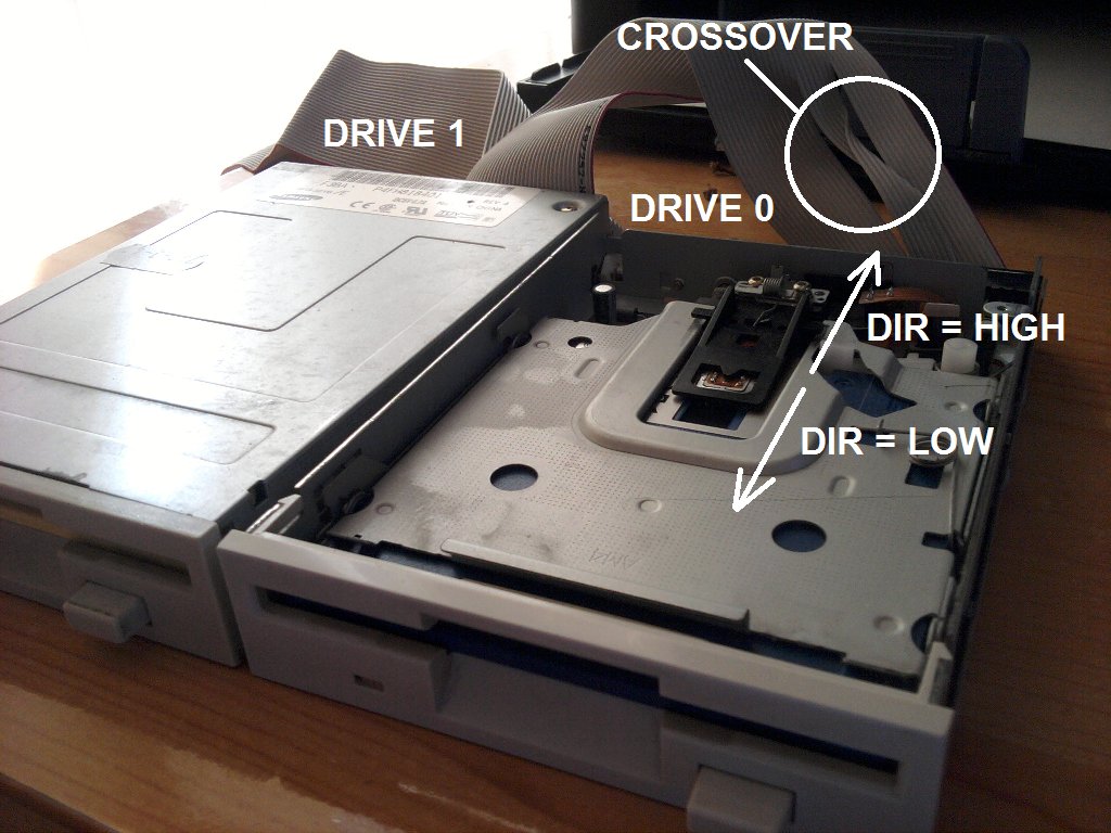
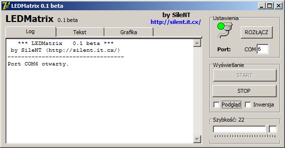
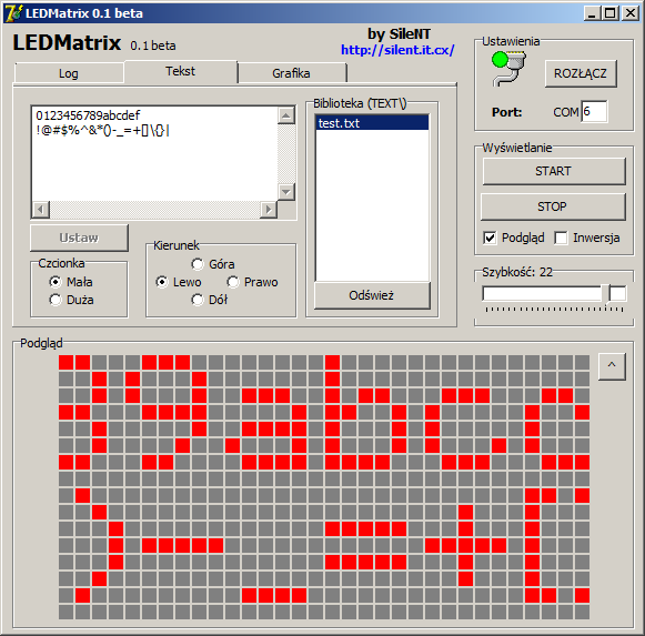
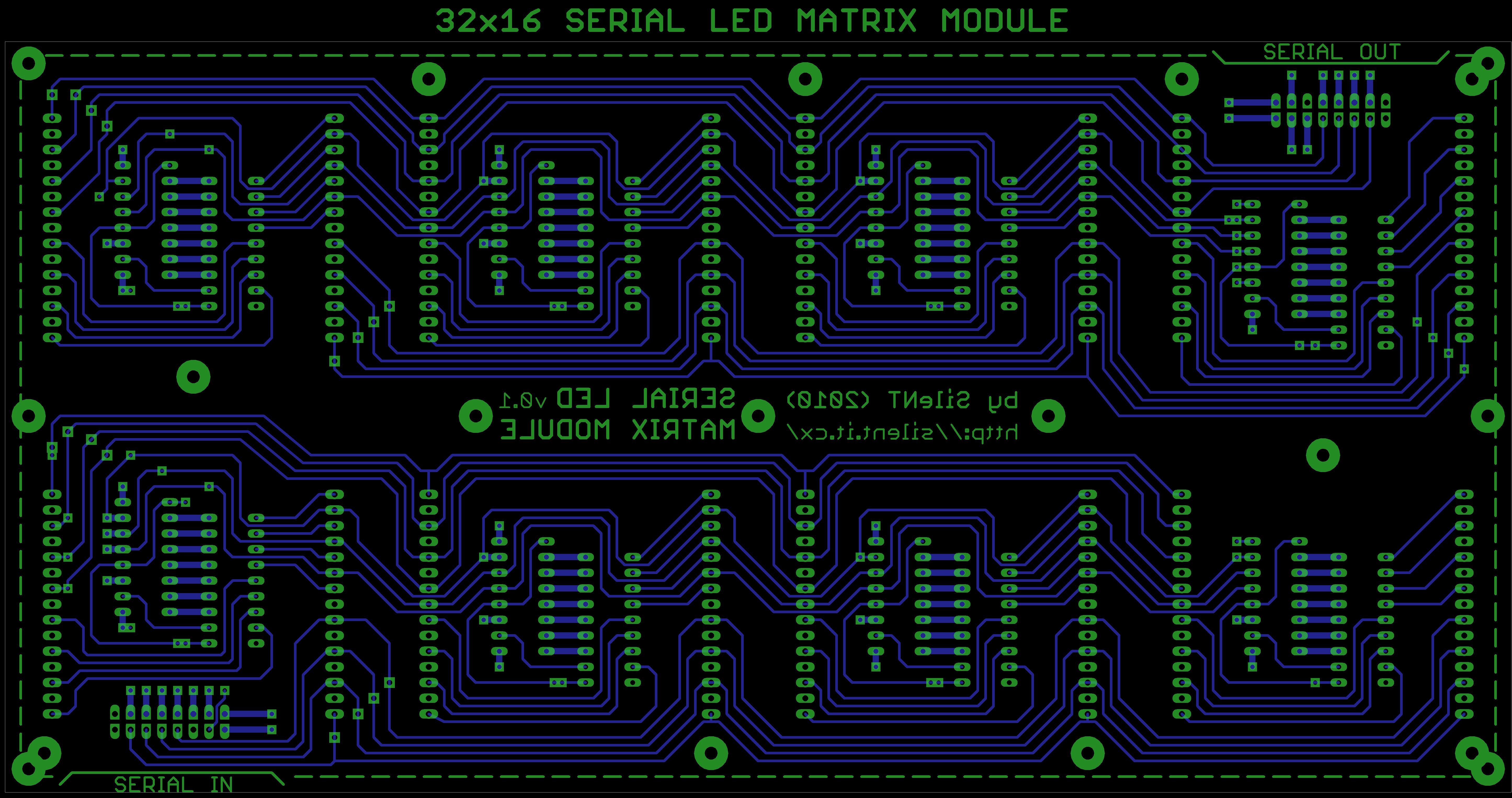
  Pobierz plik: ledmatrix/lm_layout_v_0_1.png
  Rozmiar: 732.37 KB
Warning: mysqli_num_rows() expects parameter 1 to be mysqli_result, boolean given in /home/ebiwptr/silent/home/filedb.php on line 99

Zapraszam do komentowania i zadawania pytań!

wrz 262010
 

*** AKTUALIZACJA: 2010-10-03 – czytaj niżej ***

Dawno tu nic nie pisałem…
Ostatnio zacząłem budowę matrycy LED, składającej się z dwóch modułów 32×16, które będzie można ułożyć w prostokąt 64×13 lub kwadrat 32×32.

Budowa jest dość prosta – standardowa konstrukcja z szeregiem rejestrów przesuwnych z zatrzaskami połączonych z 8 wierzami multipleksowanymi na zmianę. Wyświetlacz tworzą matryce LED 8×8 (5mm) kupione niedawno na Allegro w dobrej cenie.

Jak dotąd złożyłem pierwszy moduł. Płytkę zaprojektowałem w Eagle’u i wykonałem metodą termotransferu. Pomimo swojego rozmiaru, wyszła bardzo dobrze – tym razem zamiast żelazka użyłem laminatora do dokumentów, który kupiłem niedawno w Lidlu za 49,99 ;-). Być może niedługo napiszę o tym więcej.

Wiercenie i lutowanie podstawek okazało się dość męczące – na płycie znajduje się około 600-700 otworów. Matryce umieściłem na podstawkach pod goldpiny – wchodzą dość ciężko, ale jeszcze się mieszczą. Całość jest niestety mało sztywna – następny moduł będzie na grubszym laminacie (1,6mm).

Całość jest sterowana przez mikrokontroler ATMega32 na mojej uniwersalnej płytce testowej. Docelowo animacja będzie przesyłana z komputera przez RS232 (COM lub adapter USB-RS232) w czasie rzeczywistym lub będzie ją można wgrać na stałe do sterownika. Aktualnie jest ona wkompilowana w program.

Panel prezentuje się następująco:


W rzeczywistości nie mieni się tak jak na filmie.

Aktualnie zabieram się za pisanie programu w C dla mikrokontrolera do odbioru danych z komputera oraz drugiego programu dla PC do obsługi wyświetlacza.
Oprócz tego do zrobienia został jeszcze projekt płytki sterownika oraz drugi panel.

Jak skończę projekt, opublikuje schematy \ layouty PCB oraz programy.

*** AKTUALIZACJA: 2010-10-03 ***

Projekt idzie do przodu – dzisiaj skończyłem pisać wstępną wersję programu do komunikacji z wyświetlaczem. Software posiada podstawowe możliwości – przewijanie tekstu w każdym kierunku, wyświetlanie monochromatycznych grafik BMP – jako animacja lub przewijany obraz statyczny. Ciekawym dodatkiem jest plugin do Winampa, który wyświetla na żywo analizator widma.

Sterownik matrycy komunikuje się z PCtem za pomocą RS232. Prędkość transmisji 115,2 kBaud\s w zupełności wystarczy do wyświetlania płynnej animacji, jak i do wyświetlania analizatora widma. Przy dwóch panelach 32×16 sterownik powinien uciągnąć 50-60 klatek\sek.

Demo #2 – tekst, grafika i spectrum analyzer:

Do zrobienia pozostał drugi panel, mniejsze poprawki w protokole transmisji i dodanie funkcji wyboru rozmiaru matrycy w sofcie dla PC (32×16 \ 64×16 \ 32×32). Niedługo opiszę dokładniej cały projekt.