Paweł Zadrożniak

cze 132022
 

After a long time it’s time for a big upgrade of my computer hardware orchestra. Here it is! The bigger and better Floppotron 3.0. 512 floppy disk drives, 4 scanners and 16 hard disk drives.

My noise-making contraption grew a little bit since last update. It has its own „studio” space and became a relatively complex device. There is a ton of cables, a lot of custom electronic circuits, but the whole power is in the firmware which has been rewritten from scratch. In this article I’ll try to explain the principle of operation, how it’s built, how the whole system works, what’s still missing, provide some more technical details for nerds and answer the most commonly asked questions.

So how does it all work?

To avoid scaring the non-technical readers away at the beginning, I’ll start with the basic operating principles and explain where these sounds come from. Every mechanical device with electric motor or any other moving parts makes noise as a side effect. Sometimes that noise can be controlled. and turned into music – which usually involves some level of abuse. All of the devices present in the „orchestra” contain either stepper motors or moving heads (in case of hard drives), which are driven by custom electronic circuits – controllers. Those controllers are connected in a network and can be commanded from the computer to make a specific device (e.g. scanner #2) emit a specific sound (e.g. constant 440hz tone which corresponds to A4 note in music) at a specific point in time. A sequence of those noises and tones makes music – just like with the real instruments. Sounds simple? In principle, yes, but it gets complicated in a larger scale.

How it’s done?

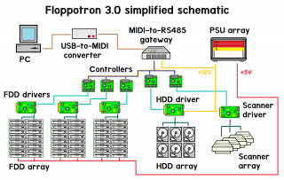
The machine evolved into a relatively large system with multiple custom circuit boards and 3D-printed parts. While making the new Floppotron, one of the main priorities (if not the main) was finishing it in reasonable time. It’s still a hobby project made after hours and not something commercial or mass produced, so you will find some nice solution as well as some janky, quick-and-dirty ones – and that’s the beauty of hobby projects. Let’s get a little more technical. To explain how the system works, I’ll go through the overview first and then will get into details of each individual block. Here’s a simplified schematic od the machine.

To make the old computer hardware play, we need a set of electronic controllers mentioned before but also a proper music (musical sequence) to play. A melody is encoded as a sequence od MIDI events, the same format as all digital synthesizers use. MIDI does not carry any actual audio data, but just short events, like pressing a piano key or twisting a control knob – you can think of it as a digital form of sheet music. Those events are send from the computer to the gateway using USB to MIDI adapter. The gateway is a custom nRF52 microcontroller based device which sits between the PC with MIDI adapter and the network of „instrument” controllers. It receives MIDI data and converts that data to RS-485-based internal protocol which can encapsulate MIDI and some extra stuff. The gateway, protocol and reasoning is described in further section. Those messages are picked by controllers which will turn the digital information into a sound by driving the electric motors or moving the hard disk heads. The controller consists of a common MCU board with Nordic nRF52832 chip and a driver boards specific to the „instrument”, like floppy drive string, flatbed scanner or a hard drive. If you’re wandering why there is a Bluetooth-enabled chip – I’ll explain it too, but let’s talk about how the sound is created first.

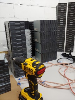
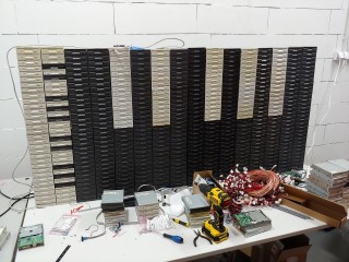
Floppy disk drive wall

A floppy disk contains a magnetic disk inside which is read and written by the drive (FDD). The data is stored by the magnetic head being moved over the spinning disk surface which incorporates two motors. One in the middle of the drive which spins the disk around and a second one driving the linear mechanism which slides the head across the disk radius. It’s the latter, stepper motor which makes that specific FDD seek sound. The head assembly is moved back and forth in small steps and each of those steps make a click. If the step rate is high enough, it is perceived as a constant tone with its pitch depending on movement speed.
   
The controller software takes care of driving multiple disk drives at once to step its heads with requested frequency. There is also one more thing which makes it sound good and more natural – it’s the sound envelope simulation. The drives are grouped in columns by the software and the whole column can only play one tone at a time, but with varying number of drives playing. By changing the number of active drives I can make the tone volume change over time and mimic piano keystrokes or plucking guitar string which volume decays exponentially. The envelope can also be used to get other nice sounding effects, like vibration (sinusoidal envelope), etc.

Driving a single FDD is easy, as it provides a simple digital interface to control the head position on its 34-pin connector. To move the head, only 3 signals are required – EN (enable), DIR (direction) and STEP. The head step is performed on falling edge of STEP signal in a direction selected by DIR pin state, provided that EN is active (logical „0”), which also lights the LED on the front of a drive. Connecting and driving a larger amount of drives makes it a little more complicated.
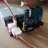
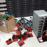
 
To connect that many drives, I made a set of daisy-chained adapter boards containing buffers and shift registers (driven with SPI) providing more outputs. Generating the signal sequences for that many drives is tricky, but I was able to get a pretty god performance with some programming tricks and by using PPI (a special peripheral present in Nordic chips) to offload a signifiant part of the signal generation from the CPU. In current configuration, one controller drives up to 192 drives, so I’m using 3 controllers to drive 512 FDDs. More drives per controller is still possible with some further optimization (to keep the satisfying timing resolution), but it’s not really needed at this point.

     
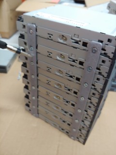
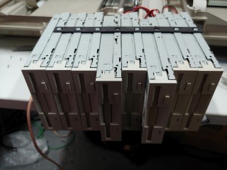
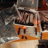
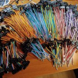
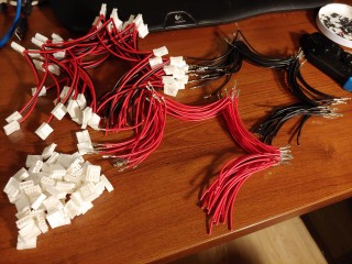
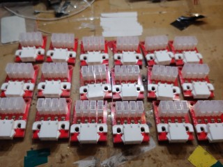
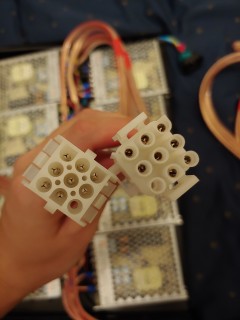
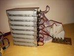
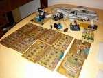
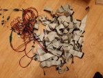
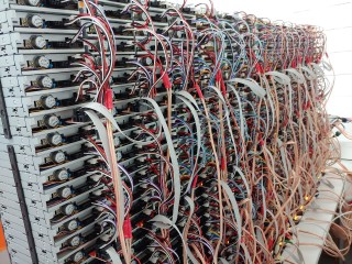
The FDD wall is made of 8-drive blocks tied together with 3D-printed rails. Every block has one adapter (assembled in local SMT manufacturing facility) plugged into the first drive. The remaining seven drives are connected to the adapter outputs with hand-made cables terminated with Dupont connectors. The cabling was the most tedious part. I was planning to order such cables in a local factory, but due to lead time exceeding a couple of month I decided to go a quick-and-dirty way. I have ordered a bag of so-called rainbow cables in hobby shop, removed the 1×1 plastic connectors with a knife ((512 – 64) drives * 4 wires * 2 sides!) and put the larger 2-row connectors. I was also initially experimenting with a multiple IDC 2,54 connectors on a single ribbon cable (to avoid cable mess like in previous FLoppotron) – it went pretty good, but required assembly of tinny PCB adapter for every drive which would also increase time and costs. I went with the solution which maybe does not look that cool, but was faster, hassle-less, and cheaper. I couldn’t find any pre-made cables for FDD power, so I had to make those cables and crimp the connectors by hand. Every stack of drives has a 3D printed base which holds the controllers and power boards with resettable fuse. There is one dedicated resettable fuse with indicator LED per each 8-drive block, so failing (shorting) drive with shutdown the block until the short is removed. That protects the cables and makes the replacements of (up to 30-year old) failed drives easier – which, by the way, do fail occasionally. Plastic base with thin plastic rails is not the sturdiest construction, but that will do for now.


Flatbed scanners

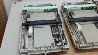
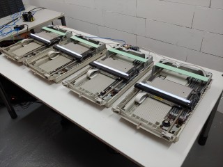
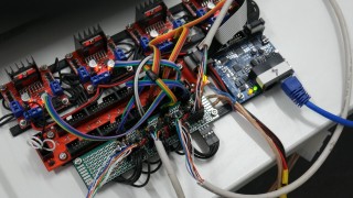
The floppy disk drives do a good job playing low pitch tones, but does not handle high notes well. It’s a task for flatbed scanner motors. They have larger motors and can play higher pitch sounds. To drive the scanner motors, I have build a prototype driver using one of my previous prototype output boards combined with off-the-shelf H-bridge modules mounted on a 3D-printed frame. There are four old HP scanners, almost identical as the larger on in Floppotron 2.0 – it took me quite a bit to hunt them on eBay and local Polish advertisement sites. At the moment, it works in the same way as in the previous Floppotron – the controller moves the scanner head assembly using stepper motor with varying speed and alternating direction to avoid bumping against the chassis. It still does not have endstop switches and cannot automatically position itself in the center on power-up – that’s something I want to implement in the next hardware update.
  
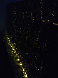
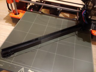
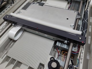
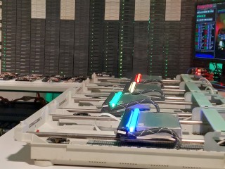
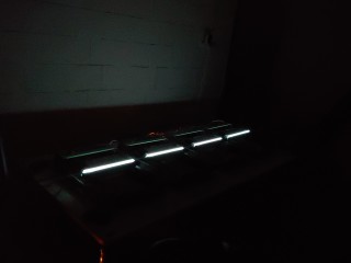
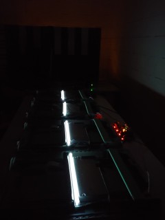
However, there are two new features. The first one is the nice looking, neon-like silicon RGB LED strip mounted on each scanner head. In addition to aesthetics, it helps in identifying which device is actually playing which section by pulsing with the notes. The strips are press-fitted into a 3D-printed rails replacing a part of metal housing and scanner mirror assembly. The second new feature comes with the entirely new software and MIDI support – pitch and modulation effects has been improved. Now the scanners can make even more weird sounds.


Hard disk drives

The clicking sound of the hard disks is produced by energizing the coil in the magnetic head assembly. That head is effectively a speaker – but unlike in case of speakers, the element being moved is an arm with magnetic read/write head instead of a speaker cone. In normal operation, the head is moved back and forth over disk platters within the safe operating region. When pushed too far, it will hit the boundary and make a loud click – something you really don’t want to happen with a live hard drive storing your data.

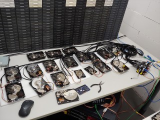
Some time ago I bought a couple of small lots of random old hard drives on eBay-like services. Every drive model has slightly different mechanics, has a different metal casing and therefore make a different sound when abused. To make the set of hard disks sound a little more like a drumset, I had test each drive and sort them by sound they make. Some drives make a bassy „clack”, some of them make higher „bang” and some of them sound like a bell. Each one of 16 drives in current setup has been assigned to a closest General MIDI drum sound it can mimic, e.g. kick drum, snare or closed hi-hat.
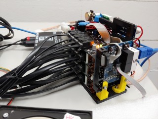
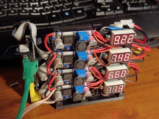
    
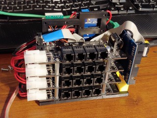
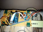
Unlike the scanner controller, the hard disk controller is more complete. The controller is a bundle of boards tied with wires and 3D-printed prototype frames. There is a single common controller board with dedicated software (as in all other controllers), and a chain of custom H-driver boards in pair with off-the-shelf voltage regulator board (with a cheap clone of LM2576/LM2596/etc) – one pair per every group of 4 drives.

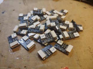
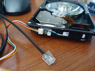
To connect HDD heads I have used modular 6p6c (RJ12) connectors (which are very common and easy to crimp) and a flat 6-conductor phone cable I had laying around. It’s not the best way to carry power due to its thin wires and high resistance, but it’s way thinner by common UTP cable and running 16 of those on a table look way more clean. Aesthetics are also important in this kind of project, so if it works – it’s good enough. Every hard disk has been equipped with a tiny hand-soldered board containing RGB LED and a cable connector. As with scanners, the flashing LEDs help identify which drives are playing.
   

Controllers, gateway and communication

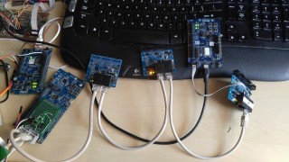
The instruments are exposed to the PC as a MIDI device using USB-MIDI adapter connected the gateway – another custom device with 3D-printed case. I wanted to connect all the instrument controllers in star topology (instead of a daisy-chain as it could be done with MIDI), so I built a converter box with MIDI interface on one side and RS485 network on the other side. With that architecture, the orchestra can be up-scaled easily.
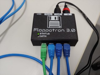
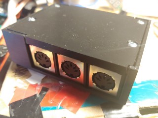
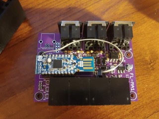
As a connectors I have used modular RJ45s which provide data and +12V power to the controllers. RS485 lines are shared, so controllers have two RJ45s and can be daisy-chained to shorten the cable run. While a passive MIDI-RS485 converter could technically work (as MIDI is a serial interface with a current loop), I made it more complex to get features like checksums, etc. The converter is based on nRF52840 module and a custom baseboard with MIDI/RS485 transcievers and connectors. The software converts MIDI serial data to internal RS485 protocol at higher baudrate (a similar protocol to Modbus). It also has some more features like scanning the internal network and even software updates of controllers behind the gateway over MIDI. It can also be expanded in future. NRF52840 has USB device hardware, so USB-MIDI could optionally be implemented directly in the gateway to bypass low MIDI baudrate limitation (31250) in case of adding multiple new devices into the network. DMX lighting over MIDI is also a possible option.

    
The controllers include a common MCU boards and instrument-specific driver circuits. For a quick and easy development, I have picked a platform I know well and have worked with for a couple of years on daily basis – nRF52 (Nordic Semiconductor) ARM Cortex-M microcontrollers. It’s a Bluetooth LE-enabled MCU family (which I’m not using in this project) with a couple of other very useful features. The main two worth pointing out are fully remappable pins and PPI peripheral which allows to trigger actions by events generated by other peripherals without CPU interaction.

Great power comes with great energy bill!

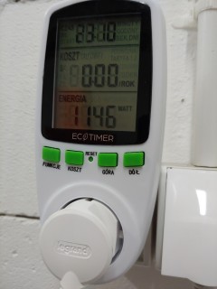
With increased size, power demand has also increased significantly. Two PC ATX power supplies are not going to cut it anymore. While scanner moors and hard disk heads don’t need a lot of power, 512 Floppy disk make the numbers go high. One drive consume a relatively large amount of power when making noise – up to 2-2,5W (0,4-0,5A at 5V) depending on drive model and frequency. One stack of 32 drives can draw up to around 16A of current when all drives are active. In a typical use case the average current is lower, usually 20-30% depending on music being played. The whole stack is (usually) active for only a short period of time as the controller varies the number of playing drives to alter the sound volume in time. Adding the numbers – 16 stacks may theoretically consume 1,28kW in peak (I have measured at most around ~1,15kW with all 512 drives buzzing).
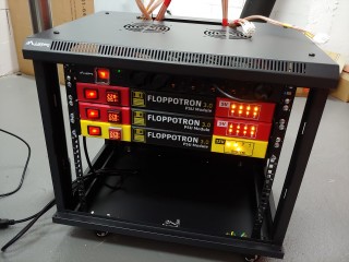
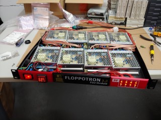
     
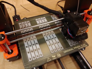
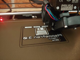
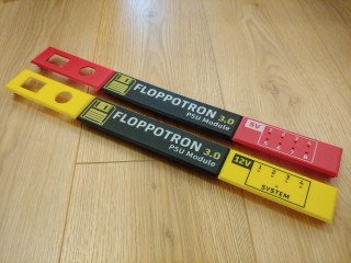
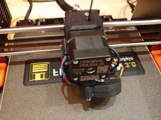
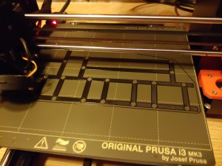
To power the drives, I have used an array of 16 modular 5V/18A power supplies – 18A of continuous current provides a large buffer, even if I wanted to go 100% power for some reason. Every module has built-in over-temperature and short protection. The smaller modules have some advantages over larger PSU with higher specs (>200W) which fit this project very well. They are cheap ($18-$20 each), they have no fans, and the case is low-profile so the modules can be placed on 1U rack shelf. I have considered mounting those modules behind every FDD stack to avoid thick cables for up to 16A, but have eventually decided to install them on perforated 1U shelves inside of 19″ rack cabinet. That turned out to be a good decision, because there is no high voltage cables outside the rack, switching mode supplies can become noisy under load (especially when there are 16 modules) and the biggest advantage – case was built without putting much effort using off-the-shelf parts. There are also some extra aesthetic elements – 3D-printed front panels for PSU modules. I have designed the 3-part panels in Fusion 360 and printed them with Prusa MK3s 3D-printer on a textured base plate. If you’re curious about the labels – I made them by printing the texts on the bottom layer and switching filaments. In general, 3D-printer did a nice job in this project.

        
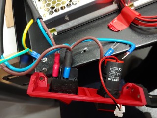
One suspicious thing in the above pictures that might have caught your attention is the cable color. Yes, that’s a 4mm² speaker cable. I know, I know, that definitely does not meet the safety standards because of the insulation thermal parameters… but it’s not an industrial machinery. …and the cable was pretty cheap. At least it’s a pure copper cable, not one of that coated aluminum crap. The cables are terminated with fat 6,35mm connectors which can handle the maximum load. The whole cabinet is protected with softstart module. That prevents the PSU module array with high input capacitance from tripping the breaker on powerup.

How the music is made?

The device is MIDI-compatible, which means I can use any music composer software which can output MIDI or save MIDI files. Note sequences are encoded as MIDI events, placed on up to 16 tracks. Each track can be assigned to a specific section in the orchestra by changing its program (instrument) parameter. The specific floppy drive stacks play bass tracks, guitar or piano tracks and some of the drum sounds. Hard disks are assigned to drums and scanners play lead tracks. Instruments (or program numbers) can be selected from the list in any MIDI editing software.
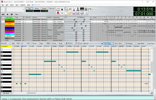
To create an arrangement, I usually start with already existing MIDI file. If I cannot find one, I have to make it from scratch – from hearing or using sheet music when available. Even if there is an existing MIDI for a specific song, re-arranging it for The Floppotron is still a time consuming process. Every „instrument” in the setup have its limits and the track must fit the note range it can play. Making a track sound good on the stacks of FDDs or a scanner usually involves a lot of tweaking. I also spend some time to add the fine details, like slides (portamento) or vibratos to mimic the quirks in vocal or guitar parts of original songs – these has to be recreated by ear. Making one arrangement for 3.0 usually takes me 3-4 evenings, which is a little longer than for the older Floppotron 2.0.

Other software

Along with the controller firmware, there is also some software on the PC side. Controllers are configured using dedicated application written in Python. It allows me to set the parameters like connected instrument type or MIDI mapping table. It can also update the firmware in every controller over MIDI port.
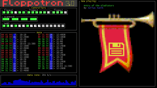
There is also one more application used for visuals only – a colorful retro-looking text terminal showing the machine status. It’s also a Python application using Urwid TUI library (running under Cygwin/XTerm on Windows).

What’s next?

The next step will be making some videos with the new setup. There are also some minor software bugs to fix and some missing stuff to add – like endstops for scanners. In the future, I’m planning to add some new instruments, like dot matrix printer and maybe some automated lighting. We’ll see.

More music covers coming soon!
lip 062016
 

Remember the famous floppy drives? They’re back… with multiplied force (yes, THAT „force”) and some friends!

I have bought some more drives in order to expand the previous project back in 2012, which spent four years in a carton box. Together with new floppy drives, some more hardware has arrived: hard disk and optical scanners. Now I have the whole computer hardware orchestra – 64 floppy drives, 8 hard disks and 2 scanners – The Floppotron.

How does it work? The principle is simple. Every device with an electric motor is able to generate a sound. Scanners and floppy drives use stepper motors to move the head with sensors which scans the image or performs read/write operations on a magnetic disk. The sound generated by a motor depends on driving speed. The higher the frequency, the greater the pitch. Hard disks use a magnet and a coil to tilt the head. When voltage is supplied for long enough, the head speeds up and hits the bound making the „drum hit” sound. The disk head coil can also be used as a speaker to play tones or even music, but… that would be too easy and too obvious.


Every column of 8 floppy drives is connected to one 8-channel controller built on ATMega16 microcontroller. One controller acts as one voice with envelope simulation – the higher the volume, the more drives are playing. This allows to make ADSR-like shape and simulate a musical instrument, like a piano (exponential decay) or string instrument (sine, „vibrato”). The boards which were made a few years ago, were designed as a stand-alone „players” with optional USB-to-UART bridge and was not intended to be chained. My goal was to re-use old stuff and get the job done as fast as possible, so I used the on-board ISP (which in fact is a SPI interface) connector to link 8 drivers in a SPI chain. Long SPI chain with unidirectional communication is not an example good and reliable design, but it did not require any hardware modification and took a minute to build a controller network, so let’s call it… good enough for this kind of project.


Scanner and disk head controllers share the same base with floppy controllers, but have a different „instrument interface”. For driving the coils, I used 2 push-pull outputs (H-bridge) built with discrete SMD MOSFETs. Scanner head controllers were built using of-the-shelf boards – an Arduino Uno (firmware also builds for ATMega328 using AVR-GCC / Atmel Studio; none of this Arduino crappy software and libraries was used) and L298 breakout to save time needed to draw and etch the boards. PC interface (another Arduino board) receives the data over UART (USB-UART), buffers the messages and keeps the timings while passing packets to „musical instruments” over SPI interface, so a Windows hiccup will not affect the playback. It can also be driven by anything else like Raspberry Pi, Android smartphone (with USB-UART or UART-over-Bluetooth adapter) or another microcontroller.

Host application was written in Python 2.7. I wrote it mostly on some boring lectures when I was still studying at the university, so it’s a one big mess, but… at least it does the job. It parses the simple language used for writing note sequences arranged in tracks tied to a specific controller / channel and merges those parallel tracks into one command list which is transferred over COM port. It can also partially generate „song script” from MIDI file which speeds up the „song porting” process.

Like the project? Here’s some another records.

paź 042015
 

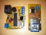
I still have an annoying analog entry phone in my flat. It does not have the numeric keypad to type the passcode and enter the staircase. I am too lazy to open the block door with a key every time I come back home, but this can be solved easily. Of course I did not mean the replacement of the entry phone with a new, digital one – that would be too easy and too obvious. Here’s my quick weekend project – analog entry phone hack, which opens the door after ringing in the secret passcode consisting of short and long rings. Traditionally, I have added some useless functionality like PCM audio playback from the SD card to make it more fun. It can play some samples, e.g. from retro games, an Arnie movie quote or… a barking dog when the guest or postman calls.


The circuit is installed in the handset. It detects the call signal and simulates the button press with a relay switch if signal matches the programmed pattern. It is also connected to the microphone output and can play the audio files on guest call or passcode input. I have built this circuit in an hour using components I had around – ATMega328P microcontroller, universal soldering board, relay, 3,3V LDO regulator and some passives.

You can download the source code and schematic below. The whole project was made in a couple of hours, so the sources looks a little messy. The circuit does not provide proper isolation from the entry phone circuit, so if you are going to built it yourself, you might want to add some optoisolators.

  Pobierz plik: entry_phone_hack_0.1.zip
  Rozmiar: 1.07 MB
Warning: mysqli_num_rows() expects parameter 1 to be mysqli_result, boolean given in /home/ebiwptr/silent/home/filedb.php on line 99

sie 092015
 

After a long break I decided to reactivate the blog. This time I have a nnew, even more useless invention – an unusual bluetooth accesory.

Most of you probably use smartphones with touch screens, but some people still prefer classic mobile phones. Now you dan dial the numbers from your little notebook just like in the good, old days!

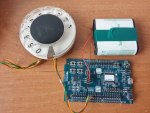
The device is based on Nordic Semiconductor nRF51422 chip (NRF51 DK board). It is recognized as a bluetooth keyboard, so no additional software is required. All you need is a phone with Bluetooth 4.0 Low Energy (BLE) support. The firmware is a modiffied HID keyboard example from the SDK, so it took me only about an hour to add a rotary dial support. The dial itself which generates the pulse dial signal was taken out of an old phone. The board could be powered from a 3V coin cell battery, but I have connected a large, flat, 4,5V battery because small coin batteries are not hipster enough!

You can get the source code below. NRF51 SDK 8.0.0 is required to build(available here). I have built it with Keil 5, but it should also work with ARM GCC or IAR compilers.

  Pobierz plik: nrf_rotary_dial.zip
  Rozmiar: 3.65 MB
Warning: mysqli_num_rows() expects parameter 1 to be mysqli_result, boolean given in /home/ebiwptr/silent/home/filedb.php on line 99

kwi 162013


It’s been awhile since my last post… Work, studies and other stuff.

Last weekend i was working on my MSc graduation project. I had to build a prototype of my circuit and unfortunately I ran out of copper laminate. I have found some old, low-quality leftovers with uneven copper layer. To improve the etching result I had to provide the constant flow of etching solution  (sodium persulfate) . I looked around my room for any items i could use and here it is! I’d like to introduce You my unique, great, wonderful, terrific, magnificent, superb, glorious, outstanding and amazing invention – a unique, great, wonderful, terrific, magnificent, superb, glorious, outstanding and amazing automatic PCB etching machine!

To build this extremely advanced device, I used an old CD-ROM drive and a strawberry ice-cream box. It must be a strawberry ice-cream. Not chocolate, vanilla, lemon or any shit, but strawberry – otherwise it just won’t work. The CD tray is controlled by one of my test boards with ATMega8 connected to drive’s eject button through the transistor and relay coil.

Yeah, it’s a little dumb, but it works. A perfect solution for the fast result ;-).

PS: Stay tuned for my new project! It’s almost complete!


Dawno tu nic nie pisałem z powodu braku czasu – praca, studia, itp.
Ostatniego popołudnia zająłem się moją pracą magisterską, która wymagała stworzenia prototypu mojego układu. Niestety, skończył mi się laminat i wygrzebałem z szafy jakieś stare resztki niskiej jakości z nierównomierną warstwą miedzi. Aby polepszyć wynik trawienia, potrzebowałem zapewnić stały ruch substancji trawiącej (nadsiarczan sodu). W tym celu rozejrzałem się po pokoju za przedmiotami, które mógłbym wykorzystać i tak powstał ten oto wynalazek. Przedstawiam mój wspaniały, wyjątkowy i niepowtarzalny wynalazek, którym jest wspaniałe, wyjątkowe i niepowtarzalne automatyczne urządzenie trawiące PCB.

Do budowy tego bardzo zaawansowanego technicznie urządzenia został wykorzystany stary napęd CD oraz pudełko po lodach truskawkowych. Muszą to być koniecznie lody truskawkowe. Nie czekoladowe, nie waniliowe, nie cytrynowe, a truskawkowe – inaczej urządzenie nie będzie działać. Napęd jest sterowany za pomocą płytki testowej z mikrokonotrlerem (ATMega8) poprzez tranzystor i przekaźnik podłączony do przycisku wysuwania tacki.

Pomimo swojego wyglądu, wynalazek bardzo dobrze wykonuje zadanie – płytka wytrawiła się bardzo ładnie. Głupie, ale działa! 😉

PS: Już niedługo kolejny projekt.

gru 272011
 

[English translation below]

Z powodu braku czasu ostatnio nic nie pisałem. Przyszły święta i znalazłem chwilę na rozbudowę poprzedniego projektu cieszącego się sporą popularnością. Oto obiecany powrót stacji dyskietek. Tym razem jest ich aż 8, a obok nich mój panel LED 64×16, nad którym ostatnio pracowałem. Z okazji świąt… świąteczna piosenka:

Planuję napisać coś więcej na temat zasady działania oraz budowy „dyskietkowej orkiestry” oraz odpowiedzieć na najczęściej zadawane pytania, ale już nie dzisiaj – to jest temat na większy artykuł. Niedługo pojawią się kolejne melodie – subskrybuj mój kanał YouTube!

Wesołych Świąt!

—————————————-

I didn’t wrote anything since october because I was very busy last 3 months. Now I have a few free days so here’s the new video – as promised. Floppy drives are back. This time there’s 8 drives and my 64×16 LED display I was working on recently. It’s Christmas time, so… here’s some Christmas song:

I am planning to write some more detailed description of how it works, FAQ and responses and maybe the instructions how to build the „floppy orchestra”, but not today. It’s a topis for separate long article. There will be more floppy music soon, so come back later or subscribe my YouTube channel.

Merry Christmas!

paź 032011
 

[ENGLISH TRANSLATION BELOW]

2 floppy drives – $5
A microcontroller – $3
Almost 2 million views in 5 days – PRICELESS!

Witam.

Mój ostatni film – Floppy music DUO – Imperial march – Imperial March – został obejrzany prawie 2 miliony razy w ciągu ostatnich kilku dni. Został umieszczony na wielu portalach, takich jak Gazeta.pl, JoeMonster.org, Yahoo czy Reddit. Podobno dziś rano został nawet pokazany w TVN24! (Czy ktoś może to potwierdzić? 😉  ) Nie spodziewałem się aż tak dużej popularności. Dziękuje.

Jak już obiecałem, będą kolejne filmy. Obecnie jestem dość zajęty, gdyż właśnie zaczął się rok akademicki (już trzeci 😉 ), a oprócz tego pracuję nad dwoma innymi projektami. Spróbuję znaleźć trochę wolnego czasu w weekend. W międzyczasie spróbuję znaleźć jakieś stacje 5,25′.

Przepraszam za duże opóźnienia w odpowiadaniu na pytania. Zostałem zaspamowany Waszymi wiadomościami\komentarzami i potrzebuję trochę czasu żeby się przez nie przebić ;-).

Dużo osób wyraziło chęć budowy takiego urządzenia.
Czy byliby byście zainteresowani zestawami do samodzielnego montażu?

——————–

Hello!

My last video – Floppy music DUO – Imperial march – has been viewed almost 2 million times in just a few days. It hat been posted on many sites like Yahoo, Reddit, polish Gazeta.pl or JoeMonster.org. Someone said that it has even been shown in TVN24, polish news television ths morning!  I didn’t expected so much popularity. Thank you!

As I promised, I will make some new videos soon. Currently I am a little busy – two other projects and back to the university classes after summer holidays. I will try to find some time at the weekend. In the meantime I will try to get some 5,25 drives.

Sorry for the big delay in responding to your questions – I am spammed and I need some time go get through all this messages ;-).

A lot of people wrote, that he would like to build this device.
Are you interested in a self-assembly kit?

wrz 292011
 

Hello! Here’s an English translation of my previos post. My English isn’t perfect so there might be some mistakes ;-).

Summer holidays are comming to an end, I have passed all september exams and now I am procrastinating doing some dumb things instead finishing two other, more serious projects ;-).
Here’s what polish AGH University of Science and Technology students do in their free time. I’d like to introduce my another, totally useless device – a musical floppy drives.

First attempt:

And now it’s time for the double:

How does it work?

It’s nothing new and it’s very simple. The sound comes from a magnetic head moved by stepper motor. To make a specific sound, head must be moved with appropriate frequency.
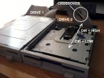
FDD has a simple interface – the description may be found for example [ HERE ]. To move the head you need to activate the drive by pulling the DRVSB0 or 1 (depends on the cable you have and the connector – notice the crossover on the FDD ribbon cable) pin low and then falling edge on STEP pin makes the head move one step in direction dependent on DIR pin state.
An ATMega microcontroller is generating those frequencies and it makes the drives play music.

Now it’s tome to call some older buddies (5,25′ or 8′ drivers) and make an orchestra!

wrz 252011
 

Niedawno złożyłem mały próbny panel 32×8, w celu zapoznania się z nowymi tajwańskimi 😉 sterownikami LED. Próby wyszły całkiem nieźle, a testowy wyświetlacz postanowiłem do czegoś wykorzystać. Wygrzebałem plugin do Winampa, który kiedyś napisałem na szybko i połączyłem go z tym wyświetlaczem. Całość prezentuje się całkiem nieźle, panel świeci mocnym jednolitym światłem, więc postanowiłem go Wam pokazać.

Na koniec smutna wiadomość. Schematów i źródeł nie będzie.

wrz 252011
 

[English translation available HERE]

Wakacje się kończą, egzaminy w „kampanii wrześniowej” zaliczone, a ja zamiast kończyć dwa komercyjne projekty zajmuje się głupotami – bo jak wiadomo głupoty cieszą najbardziej 😉 .
Oto, co robią studenci AGH w Krakowie w wolnym czasie. Przedstawiam mój kolejny, kompletnie bezużyteczny wynalazek – grające stacje dyskietek.

Pierwsza próba:

A teraz czas na duet:

Nie jest to nic nowego. Zasada działania jest bardzo prosta. Dźwięk powstaje poprzez ruch głowicy, która jest przesuwana krokowo z odpowiednią częstotliwością. Opis interfejsu można znaleźć np. TUTAJ. Wystarczy jedynie aktywować stację przez podanie stan niskiego na DRVSB0 lub 1 (w zależności czy mamy taśmę z crossem i do której wtyczki podłączona jest stacja) i wybrać kierunek ruchu głowicy (stan niski\wysoki na DIR), a zbocze opadające na STEP spowoduję ruch głowicy o jeden krok. Całością steruje mikrokontroler ATMega.

Teraz tylko pozostało zgromadzić kilku starszych kumpli (5,25′) i stworzyć orkiestrę! 😉