
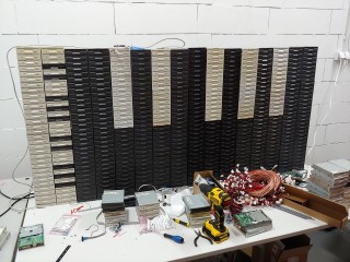
After a long time it’s time for a big upgrade of my computer hardware orchestra. Here it is! The bigger and better Floppotron 3.0. 512 floppy disk drives, 4 scanners and 16 hard disk drives.
My noise-making contraption grew a little bit since last update. It has its own „studio” space and became a relatively complex device. There is a ton of cables, a lot of custom electronic circuits, but the whole power is in the firmware which has been rewritten from scratch. In this article I’ll try to explain the principle of operation, how it’s built, how the whole system works, what’s still missing, provide some more technical details for nerds and answer the most commonly asked questions.
So how does it all work?
To avoid scaring the non-technical readers away at the beginning, I’ll start with the basic operating principles and explain where these sounds come from. Every mechanical device with electric motor or any other moving parts makes noise as a side effect. Sometimes that noise can be controlled. and turned into music – which usually involves some level of abuse. All of the devices present in the „orchestra” contain either stepper motors or moving heads (in case of hard drives), which are driven by custom electronic circuits – controllers. Those controllers are connected in a network and can be commanded from the computer to make a specific device (e.g. scanner #2) emit a specific sound (e.g. constant 440hz tone which corresponds to A4 note in music) at a specific point in time. A sequence of those noises and tones makes music – just like with the real instruments. Sounds simple? In principle, yes, but it gets complicated in a larger scale.
How it’s done?
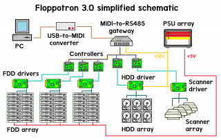
The machine evolved into a relatively large system with multiple custom circuit boards and 3D-printed parts. While making the new Floppotron, one of the main priorities (if not the main) was finishing it in reasonable time. It’s still a hobby project made after hours and not something commercial or mass produced, so you will find some nice solution as well as some janky, quick-and-dirty ones – and that’s the beauty of hobby projects. Let’s get a little more technical. To explain how the system works, I’ll go through the overview first and then will get into details of each individual block. Here’s a simplified schematic od the machine.
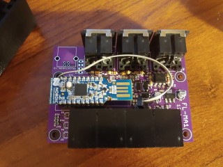
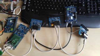
To make the old computer hardware play, we need a set of electronic controllers mentioned before but also a proper music (musical sequence) to play. A melody is encoded as a sequence od MIDI events, the same format as all digital synthesizers use. MIDI does not carry any actual audio data, but just short events, like pressing a piano key or twisting a control knob – you can think of it as a digital form of sheet music. Those events are send from the computer to the gateway using USB to MIDI adapter. The gateway is a custom nRF52 microcontroller based device which sits between the PC with MIDI adapter and the network of „instrument” controllers. It receives MIDI data and converts that data to RS-485-based internal protocol which can encapsulate MIDI and some extra stuff. The gateway, protocol and reasoning is described in further section. Those messages are picked by controllers which will turn the digital information into a sound by driving the electric motors or moving the hard disk heads. The controller consists of a common MCU board with Nordic nRF52832 chip and a driver boards specific to the „instrument”, like floppy drive string, flatbed scanner or a hard drive. If you’re wandering why there is a Bluetooth-enabled chip – I’ll explain it too, but let’s talk about how the sound is created first.
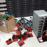
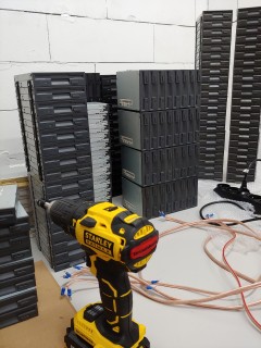
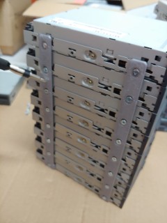
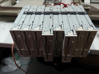
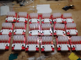
Floppy disk drive wall
A floppy disk contains a magnetic disk inside which is read and written by the drive (FDD). The data is stored by the magnetic head being moved over the spinning disk surface which incorporates two motors. One in the middle of the drive which spins the disk around and a second one driving the linear mechanism which slides the head across the disk radius. It’s the latter, stepper motor which makes that specific FDD seek sound. The head assembly is moved back and forth in small steps and each of those steps make a click. If the step rate is high enough, it is perceived as a constant tone with its pitch depending on movement speed.
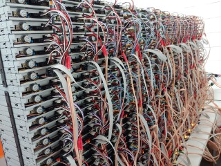
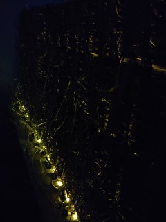
Driving a single FDD is easy, as it provides a simple digital interface to control the head position on its 34-pin connector. To move the head, only 3 signals are required – EN (enable), DIR (direction) and STEP. The head step is performed on falling edge of STEP signal in a direction selected by DIR pin state, provided that EN is active (logical „0”), which also lights the LED on the front of a drive. Connecting and driving a larger amount of drives makes it a little more complicated.
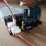
Flatbed scanners
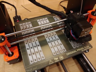
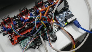
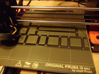
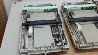
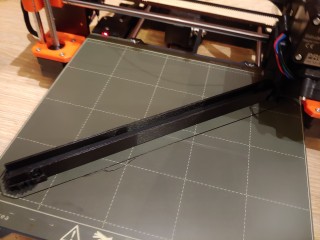
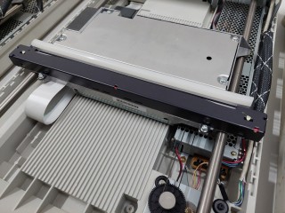
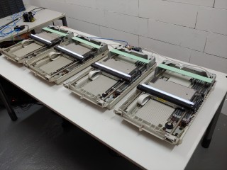
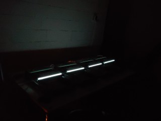
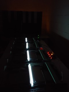
The floppy disk drives do a good job playing low pitch tones, but does not handle high notes well. It’s a task for flatbed scanner motors. They have larger motors and can play higher pitch sounds. To drive the scanner motors, I have build a prototype driver using one of my previous prototype output boards combined with off-the-shelf H-bridge modules mounted on a 3D-printed frame. There are four old HP scanners, almost identical as the larger on in Floppotron 2.0 – it took me quite a bit to hunt them on eBay and local Polish advertisement sites. At the moment, it works in the same way as in the previous Floppotron – the controller moves the scanner head assembly using stepper motor with varying speed and alternating direction to avoid bumping against the chassis. It still does not have endstop switches and cannot automatically position itself in the center on power-up – that’s something I want to implement in the next hardware update.
Hard disk drives
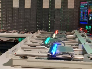
The clicking sound of the hard disks is produced by energizing the coil in the magnetic head assembly. That head is effectively a speaker – but unlike in case of speakers, the element being moved is an arm with magnetic read/write head instead of a speaker cone. In normal operation, the head is moved back and forth over disk platters within the safe operating region. When pushed too far, it will hit the boundary and make a loud click – something you really don’t want to happen with a live hard drive storing your data.
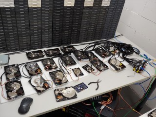
Some time ago I bought a couple of small lots of random old hard drives on eBay-like services. Every drive model has slightly different mechanics, has a different metal casing and therefore make a different sound when abused. To make the set of hard disks sound a little more like a drumset, I had test each drive and sort them by sound they make. Some drives make a bassy „clack”, some of them make higher „bang” and some of them sound like a bell. Each one of 16 drives in current setup has been assigned to a closest General MIDI drum sound it can mimic, e.g. kick drum, snare or closed hi-hat.
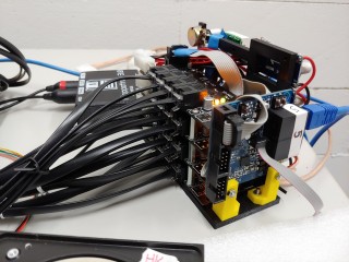
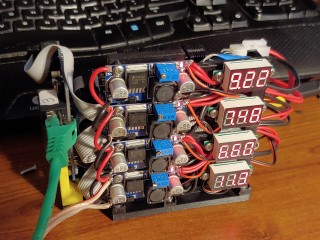
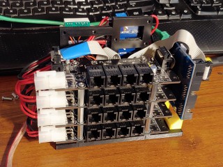
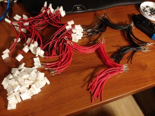
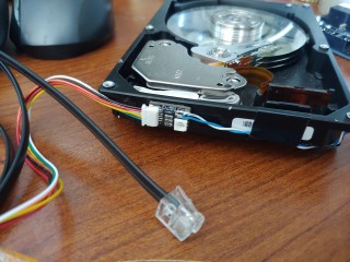
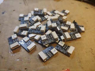
To connect HDD heads I have used modular 6p6c (RJ12) connectors (which are very common and easy to crimp) and a flat 6-conductor phone cable I had laying around. It’s not the best way to carry power due to its thin wires and high resistance, but it’s way thinner by common UTP cable and running 16 of those on a table look way more clean. Aesthetics are also important in this kind of project, so if it works – it’s good enough. Every hard disk has been equipped with a tiny hand-soldered board containing RGB LED and a cable connector. As with scanners, the flashing LEDs help identify which drives are playing.
Controllers, gateway and communication
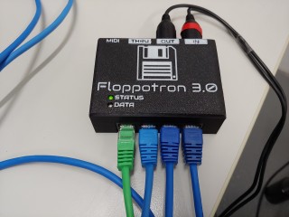
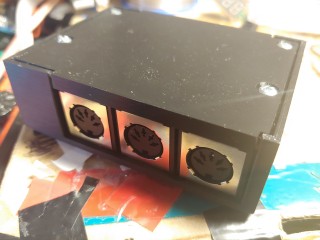
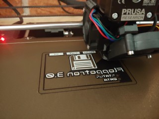
The instruments are exposed to the PC as a MIDI device using USB-MIDI adapter connected the gateway – another custom device with 3D-printed case. I wanted to connect all the instrument controllers in star topology (instead of a daisy-chain as it could be done with MIDI), so I built a converter box with MIDI interface on one side and RS485 network on the other side. With that architecture, the orchestra can be up-scaled easily.
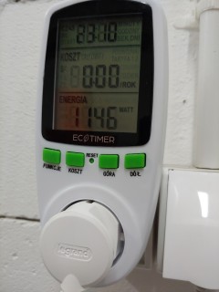
Great power comes with great energy bill!
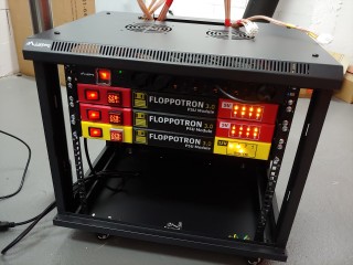
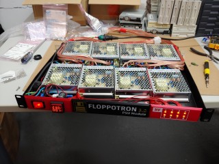
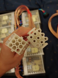
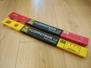
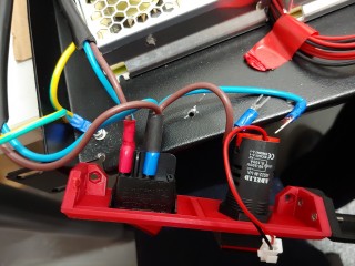
With increased size, power demand has also increased significantly. Two PC ATX power supplies are not going to cut it anymore. While scanner moors and hard disk heads don’t need a lot of power, 512 Floppy disk make the numbers go high. One drive consume a relatively large amount of power when making noise – up to 2-2,5W (0,4-0,5A at 5V) depending on drive model and frequency. One stack of 32 drives can draw up to around 16A of current when all drives are active. In a typical use case the average current is lower, usually 20-30% depending on music being played. The whole stack is (usually) active for only a short period of time as the controller varies the number of playing drives to alter the sound volume in time. Adding the numbers – 16 stacks may theoretically consume 1,28kW in peak (I have measured at most around ~1,15kW with all 512 drives buzzing).
How the music is made?
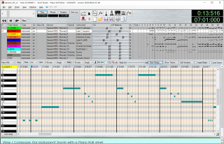
The device is MIDI-compatible, which means I can use any music composer software which can output MIDI or save MIDI files. Note sequences are encoded as MIDI events, placed on up to 16 tracks. Each track can be assigned to a specific section in the orchestra by changing its program (instrument) parameter. The specific floppy drive stacks play bass tracks, guitar or piano tracks and some of the drum sounds. Hard disks are assigned to drums and scanners play lead tracks. Instruments (or program numbers) can be selected from the list in any MIDI editing software.
Other software
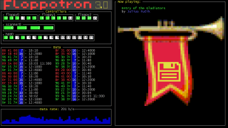
Along with the controller firmware, there is also some software on the PC side. Controllers are configured using dedicated application written in Python. It allows me to set the parameters like connected instrument type or MIDI mapping table. It can also update the firmware in every controller over MIDI port.
What’s next?
The next step will be making some videos with the new setup. There are also some minor software bugs to fix and some missing stuff to add – like endstops for scanners. In the future, I’m planning to add some new instruments, like dot matrix printer and maybe some automated lighting. We’ll see.
More music covers coming soon!
A trumpet with floppy flag means world of floppotron
Do res anyone know what happened to Pawel? It’s been over three years and he’s gone completely radio silent, no updates or messages anywhere.
Ibogaine is simply incredable, one ibogaine treatment accomplishes overnight what no rehabs can do in a month
Buy Ibogaine online
https://ibogainerehabilitation.com
Can you make it speaking with a ROBOTIC VOICE 😉 ?
alert(„Hello world”)
Since I really think it would fit the whole electronic-orchestra vibe, I’d like to ask if maybe one of the next covers in the future would be Cara Mia Addio from Portal 2? Any song from the Portal series for that matter.
Any chance we can get some of the Pokemon Trading Card Game (Gameboy) tracks played using the floppotron?
Abracadabra
Natknęłam się na ten kalkulator frekwencji, szukając sposobu na sprawdzenie obecności mojego syna w szkole. Wygląda dobrze, ale nie wiem, czy jest dokładny – czy ktoś z Was go używał? Czy uwzględnia dni wolne, usprawiedliwione nieobecności i zmiany w planie? Chciałabym mieć pewność, że mogę na nim polegać. Będę wdzięczna za każdą opinię! 😊
thats so cool! what would Walk this way and Roundabout sound with that?
You have amazed me with your music project using floppy drives, hard drives and scanners. Greetings from Spain.
Where is your music file? I forgot download the file or media, Upload the files to Media articles and required Midi files
Where is your music file? I forgot download the file or media, Upload the files to Media articles
what is the trumpet with the floppy flag on it
Copy songs need installed on the piano brackets and the inserter with music, I need hear
I want hear the song copy and upload file for Me for hearing
The song is great, Upload song and MIDI for I convert to Online sequencer conversion. But think the ED on the melody or a Remote labels and image is need upload for the printer and more for more peoples with color.
Nice
I absolutely Love The final countdown you did on 3.0
I Was wondering if you have considered actually recording the flopitron, each note etc.
That way It can be preserved for future generations.
It would also allow for others to compose music for it,
and test it out before submitting user made songs to run on the real deal !
It would be fun to run a contest for the most epic flopatron cd ever !
I would be happy to help you Organize and run it ( Im a data nerd )
When are your tour dates? I checked Ticketmaster but they don’t show you coming to a city near me.
I really want to hear this live.